Magnetic loop antenna back to start page
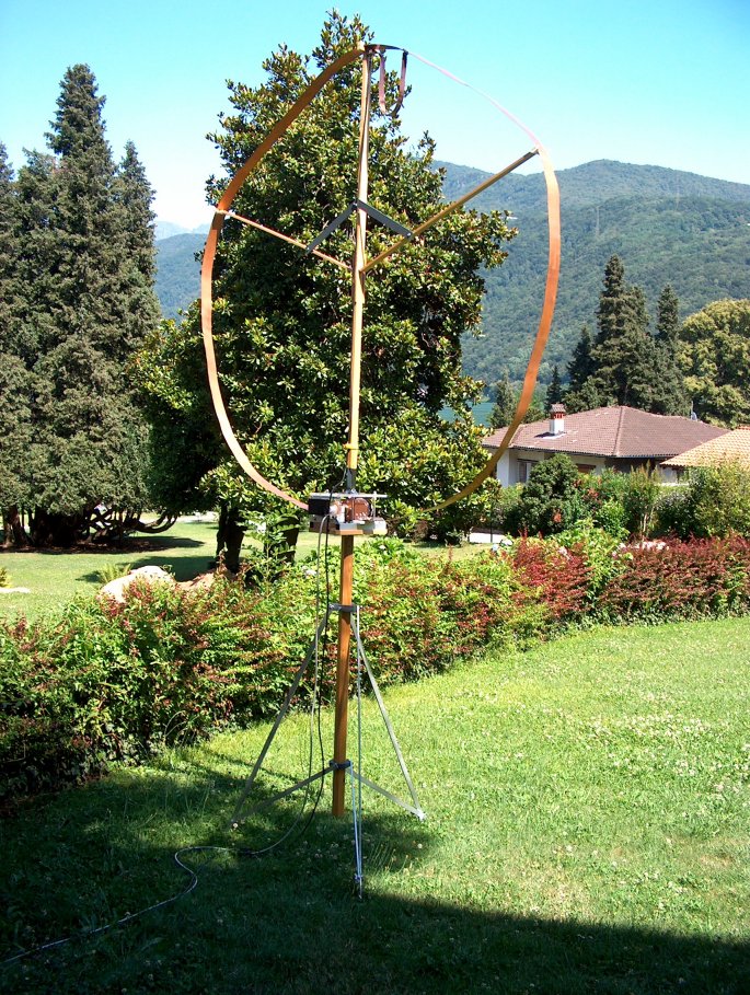
The construction of this antenna took some time and I started the project in 2003. The photo below is from summer holidays 2006, near Porto Ceresio in northern Italy, only a few meters from the lake Lugano. Beautiful place.
The Magloop has a wooden support with 3 aluminium legs. They can be folded. The loop is made of copper band (6 cm, thickness 1mm) and the diameter is about 130 cm. The feeding point is on top and the tuning capacitor (vacuum) supports the lower end of the loop. In addition to the coax feedline, a second cable serves to control the motor-driven capacitor. A potentiometer is provided to inform about the actual position of the capacitor. For safety, the antenna is on a place where other holiday guests do not have access. (Behind the trees is the south end of the lake of Lugano).
An important aspect is the feeding of the loop. I started to experiment with purely inductive coupling loops, but it was disturbing that the coupling loops needed re-adjustment upon QSY to other bands. This could be improved by the type of coupling shown here, which is a mixture of direct and inductive. When properly dimensioned, it provides a good 50 Ohm match over the entire frequency range of the loop. A crocodile clamp at the end of the inductive feeding loop allows for fine tuning of the match, depending on height over ground and near-by buildings. The match is optimized with this clamp only once when the loop is set up. No need to correct upon QSY. Below is a close-up view.

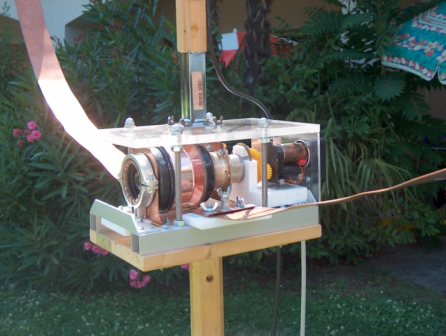
The variable capacitor /loop support unit is shown on the next two figures below. It can be used for up to 100 watts RF, probably not much more. I bought the variable vacuum capacitor on a hamfest. It is a 4 KV version (capacitance about 20-1000 pF). I used an aluminium- teflon construction. The top is made of Perspex. The motor has an in-built gear and is shielded. The potentiometer (10 turn helical) is mounted in line with the capacitor axis (also 10 turn). The potentiometer reads the capacitor´s actual position, which is indicated on the remote control unit (below). The loop can be separated from the capacitor unit within a few seconds for storage and transportation. (lake of Lugano in the background, Morcote at the teft)

Here is the magnetic loop control unit. The unit contains an SWR bridge and all the electronics needed for remote tuning of the loop. It is controlled by a microprocessor (C-Control) with a software routine I wrote in Basic. The processor serves many tasks. These include: indication of calibrated SWR (´10´ on the meter scale corresponding SWR=2), peak or average output power, actual position of the variable loop capacitor and others. The processor can automatically tune the magnetic loop to optimum SWR. The automatic tuning routine is started when I push the tuning button on the TS-50´s front panel. When the SWR optimum is found (0.5-2 seconds), tuning automatically stops and the TS-50 returns to RX in the previous mode. This feature is extremely useful because the loop resonance is very narrow and re-tuning often required. All functions of the control unit are selected by pushing one ore several of the 6 buttons on top. The front knobs are for manual tuning of the loop capacitor (course and fine). This is required when the loop resonance is too far away from the transmiting QRG (automatic tuning may fail in this case).
Here is the closed control unit:

Digital board with the programmed C-control unit:

Analog circuit, mainly for precisely servo controlling the tuning motor:

This antenna project is ongoing and under continuous re-construction.
I´d appreciate to learn about ideas and experiences from others who work on similar projects.