TL-922 modification back to start page
I found these two modifications of the TL-922 particularly useful:
- Improved relay switching with correct switching sequence
- Slow-start circuit using a solid-state relay
1. Improvement of the relay switching circuit
I reconstructed the relay switching circuit using vacuum relays and a circuit which applies the appropriate timing for relay switching. The planned switching sequence was:
1: RF out (antenna) relais
2: RF in (TRX) relais
3: Negative Ug relais
Before starting the project, I carefully analysed the switching characteristics of my rigs in order to appropriately dimension the timing characteristics of the circuit.
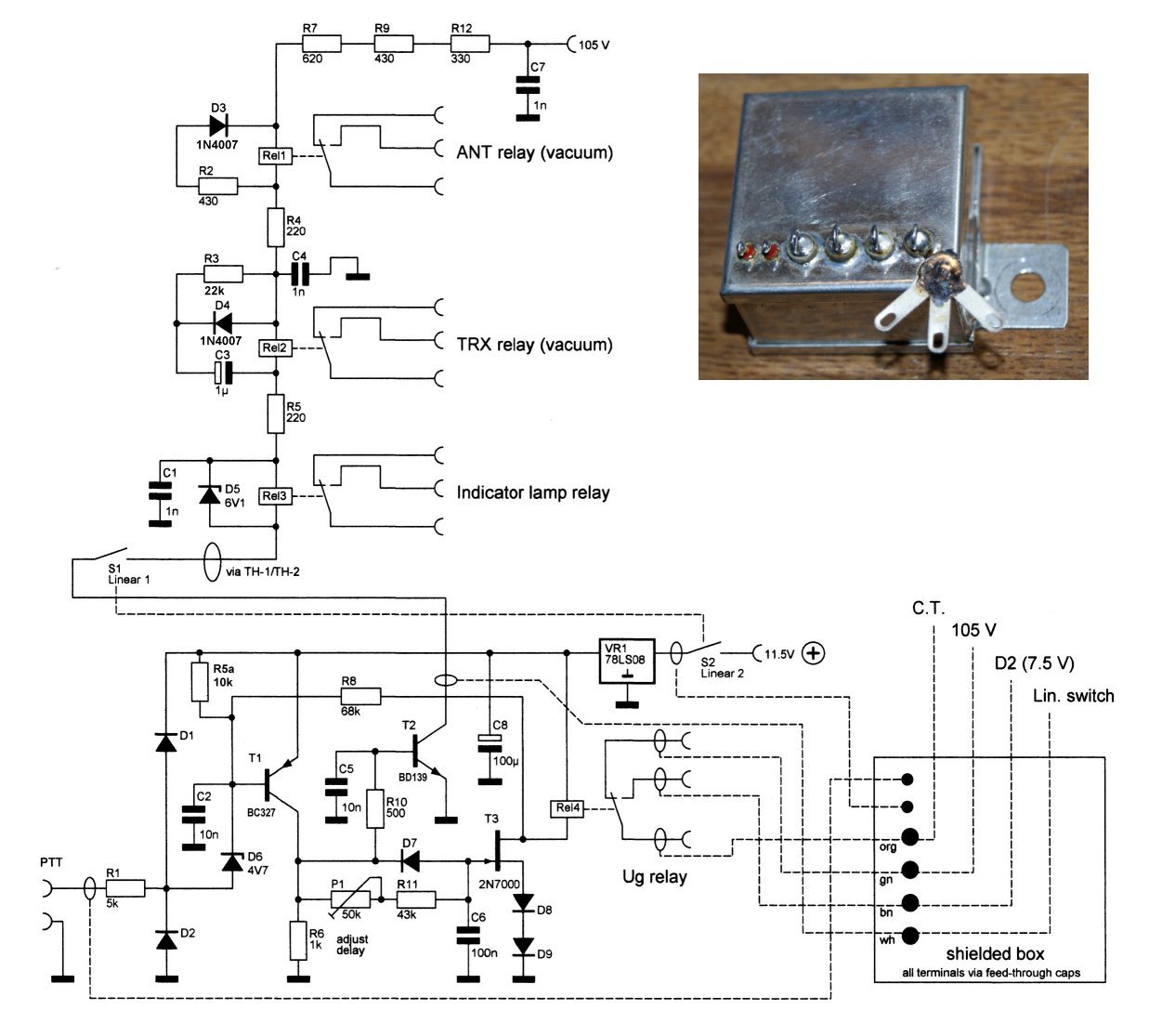
Here is the schematics of the squencing circuit (see text below for choice of vacuum relays):

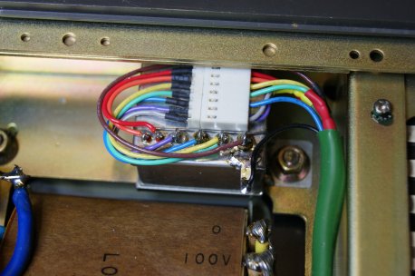
PTT is switched on if the input voltage goes low. This was necessary for my trx. For many other rigs (including Kenwood), a PTT inverter must be added for this circuit. The circuit is built into a shielded box, as shown on the top right of the circuit digram. The Ug relay is a small, fast-switching vacuum relay (10V). There was enough space in the little box, so it could be placed here. The shielded box is mounted on the chassis bottom side underneath transformer T1. This is shown here:
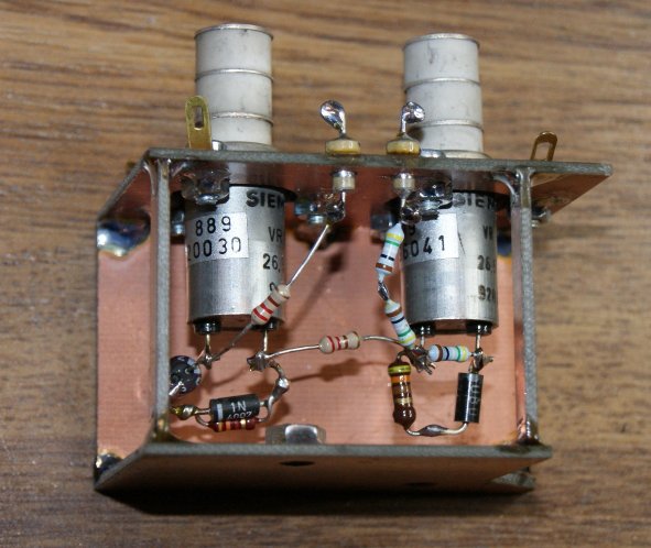
I selected two vacuum relays from different models I bought from ebay. These here (Siemens) had good switching speed, low switching noise and appropriate coil voltage & current. I noticed considerable differences in closing/opening times and bouncing, even among individual relays of the same type. I recommend therefore to examine vacuum relays in a test circuit and scope and select the best. The delay circuit shown above has been dimensioned empirically for to the selected relays. It may not be optimal for other vacuum relay types.
I mounted the vacuum relays on a holder made from epoxy, as shown below. Some parts were mounted directly on the relay coil terminals.
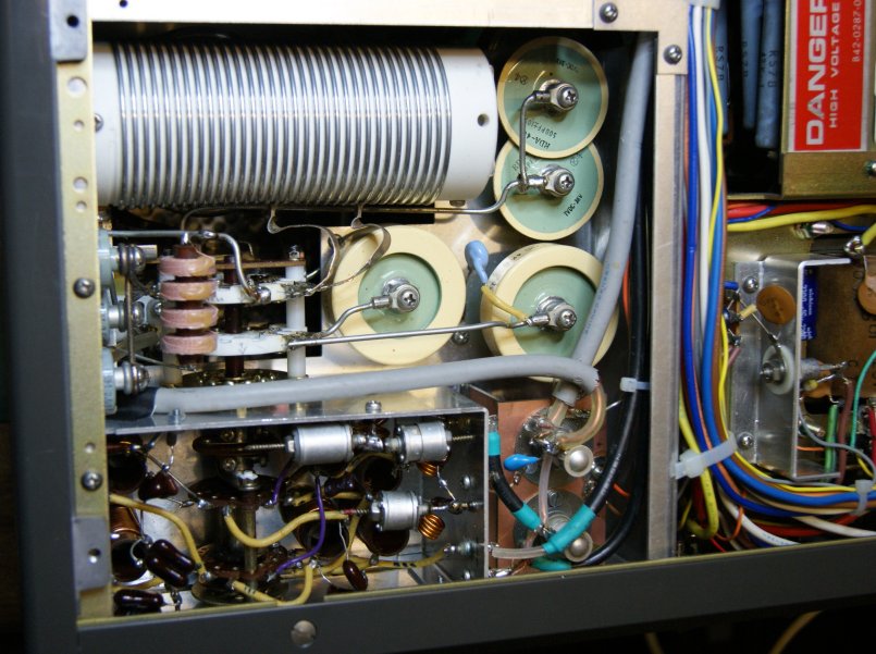
The relay holder was inserted into the TL-922 where the old antenna relay has been removed, as shown in the figure below (front of amplifier is bottom of picture). The chassis holes where the old antenna relay was attached could be re-used. You may notice that the input pi filter network has been changed. I did this to improve input matching. This is another modification not described here in more detail. Many others have reported on that.

Here is another view of the bottom side after modification. L18 (the 4-section choke coil) had to be moved to another location next to the ceramic pi network switch:
I also inserted another relay to switch the PTT indicator lamps, replacing RL-2. This new relay is located where the old Ug/lamp switching relay (RL-2) has been removed. See figure below:

2. Slow start circuit
A slow-start circuit may protect the tubes, capacitors and prevent the hosehold mains fuses to blow when the TL-922 is switchend on. The slow start circuit is built as shown here:
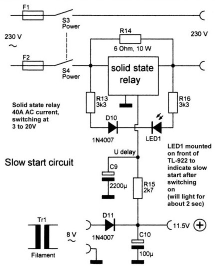
I used a solid state relay (cheaply acquired at a hamfest) which was mounted on the rear side of the TL-922. To make sure that the circuit works properly (i.e. relay shortens resistor R14) I provided a bright red LED with rectifier diode and shunt resistors. The LED indicates the voltage across the solid state relay. The LED was mounted on the TL-922 front near the on/off switch. The LED shows for about 2 seconds after switching on. In case of failure of the solid state relay the LED will not shut off. In this case the PA must be switched off manually to prevent R14 overload.
Here is a picture showing the relay mounted on the rear side of the chassis.
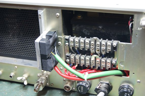
The back cover (removed here) will still fit after mounting the relay and the terminal conections are perfectly accessible through the window of the back cover.