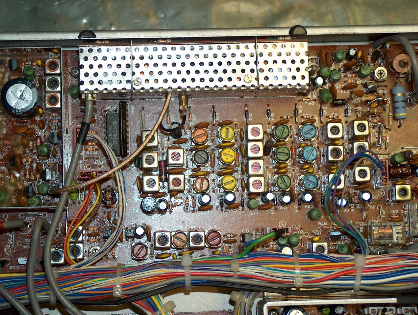

This is the new frontend mounted on top of the original one. It is held in place by two steel clamps. Three 51 Ohm resistors are visible between frontend and chassis. They are needed to reduce the 18V supply to about 12V, as required by the new unit.
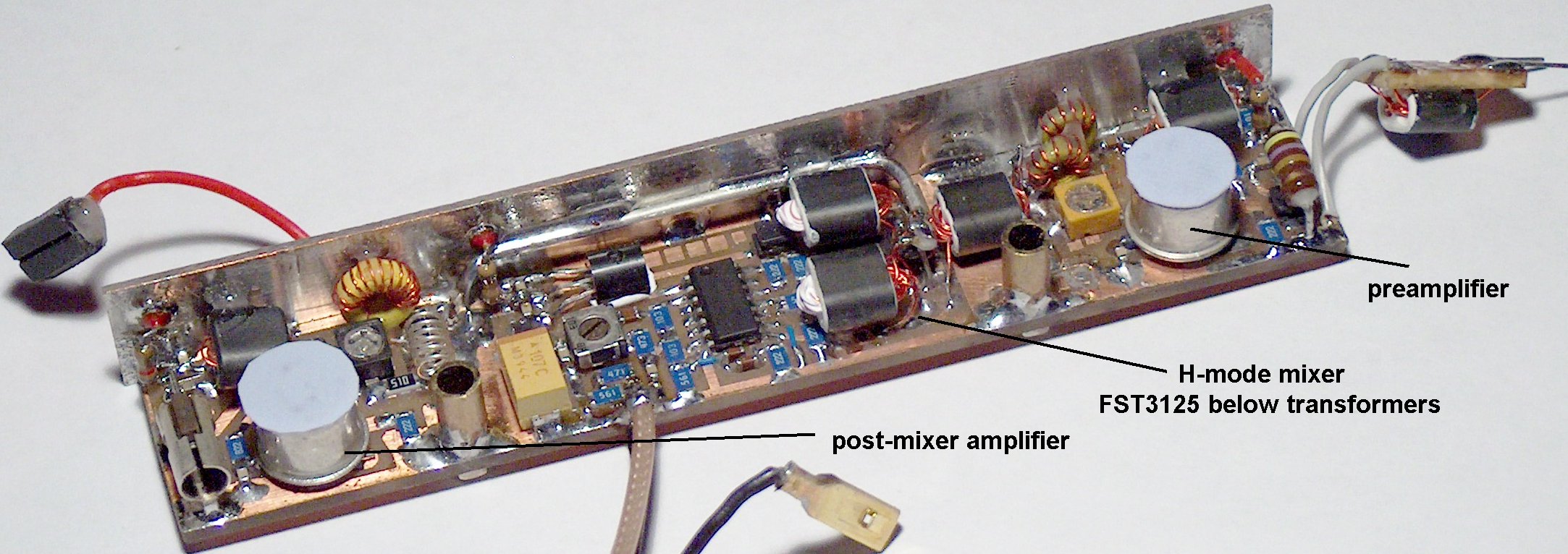
Here is the opened frontend unit. It has a 2N5109 preamplifier (Norton amplifier, about 10dB), the high level H-mode mixer uses the FST3125 bus switch. It is underneath the transformers to keep the connections short. The post-mixer amplifier is another 2N5109. There are heat conductive pads on top of the transistors. They touch the shielding top (when mounted) for heat dissipation.
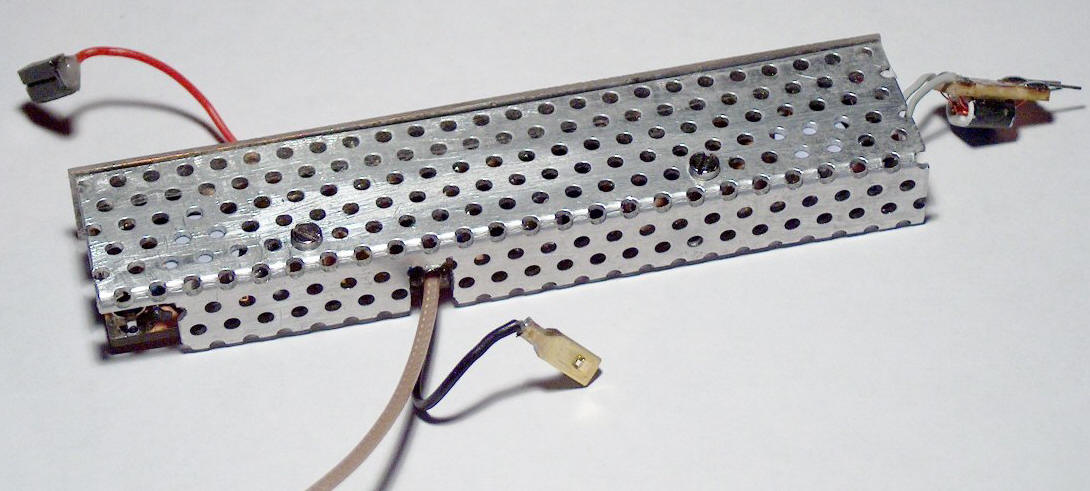
This is the unit with the shield mounted.
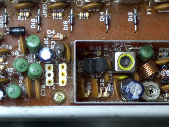
The white connector is for the input transformer of the new frontend. Only two pins are used.
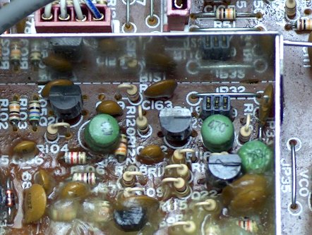
The black connector next to JP 32 couples VCO output into the new frontend. The old frontend has been disconnected.
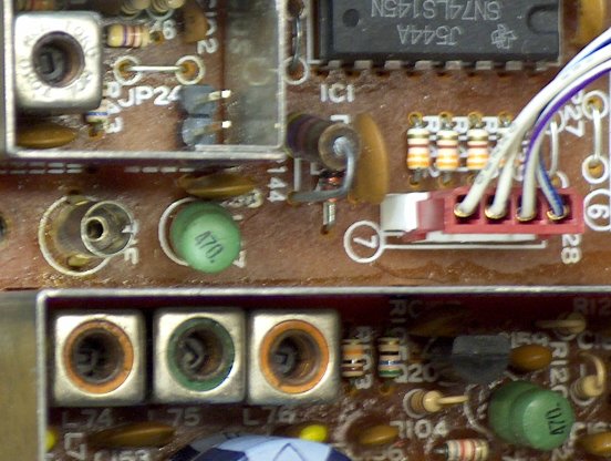
This two-pin connector next to JP24 provides positive voltage for the new frontend. The old frontend has been disconnected.
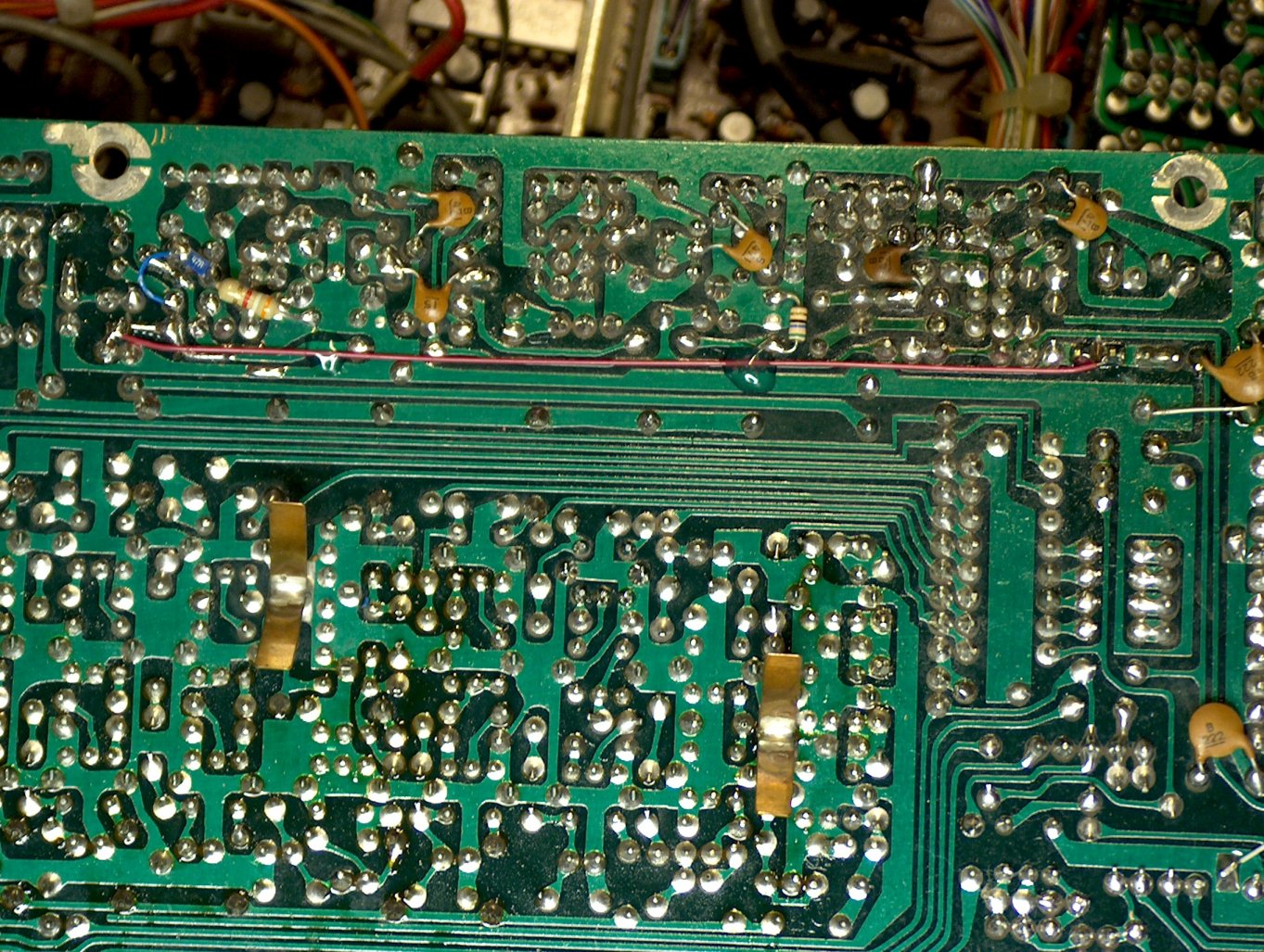
Some changes have become necessary on the RF board foil side.
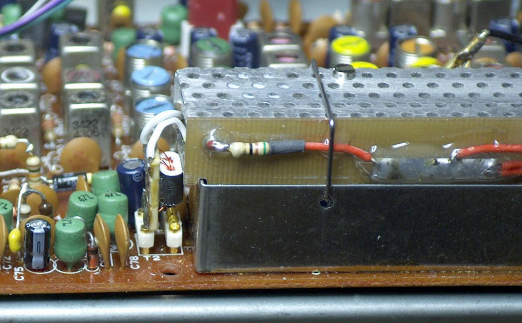
Another view of the mounted new frontend unit.